
In manufacturing, there can be an inverse relationship between speed and quality, but when making parts for aeronautics, medical devices and other complex applications, quality is fundamental. Any gains in output that compromise the safety or utility of the part aren’t gains at all. In designing additive manufacturing printers with two lasers, we faced a unique set of challenges: a second laser introduces complications that are quantitatively and qualitatively distinct from those of printing with a single laser. Through hardware and software innovations, we addressed each issue, and the result is a printer that meets our exacting quality standards and produces parts at twice the speed of a single laser.
Laser Alignment
The first issue presented by the addition of a second laser was scan-field alignment. This is a particular concern with aerospace components and other large parts. Many medical parts, such as orthopedic replacements, are small enough that each laser can create a whole part on its own. With larger parts that take up most of the build plate, the lasers have to work in concert, and, like circus performers catching each other in mid-air, a slight misalignment can have big consequences. In engineering terms, that means that each scanning system has to be aligned to the other with less than fifty microns (one twentieth of a millimeter - thinner than a human hair) difference everywhere on the build plate
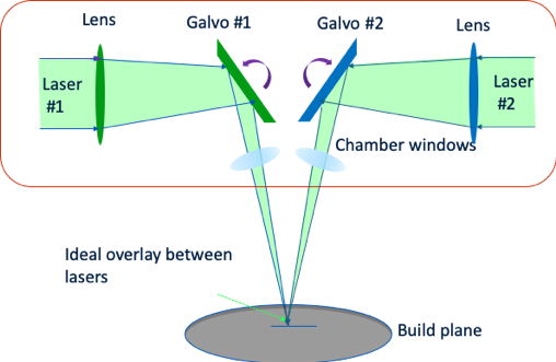
Aligning two laser spots can be accomplished with precision, but in some systems this requires external hardware. The alignment procedure often consists of burning marks on a substrate and measuring the outcome, and this can be tedious work. It is also important to perform the calibration at the build plane because any change in the distance between the scan head and the plane of measurement will cause a corresponding shift in the alignment.
The thermal state of the system also becomes an important variable. As an example, consider a build chamber made out of stainless steel where the scan heads are 500mm from the build plane. During a build, the chamber heats up. If there is even a 15°C change in the chamber temperature, the distance between the scan head and build plane can change by over 100 microns. Depending on the angle of incidence in the overlap region, this temperature change, by itself, can invalidate the calibration.
Tall parts are, therefore, a cause for concern if they are built using both lasers on a single part. Galvonometers tend to have some amount of drift in their position, and this drift accumulates over time. This means that a calibration that was valid on the first layer, or for the first 100 layers, may not be valid at layer 8,000, and the quality of the overlay may change within a single build.
 Layer 1
  Layer 8000
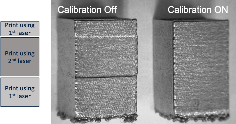
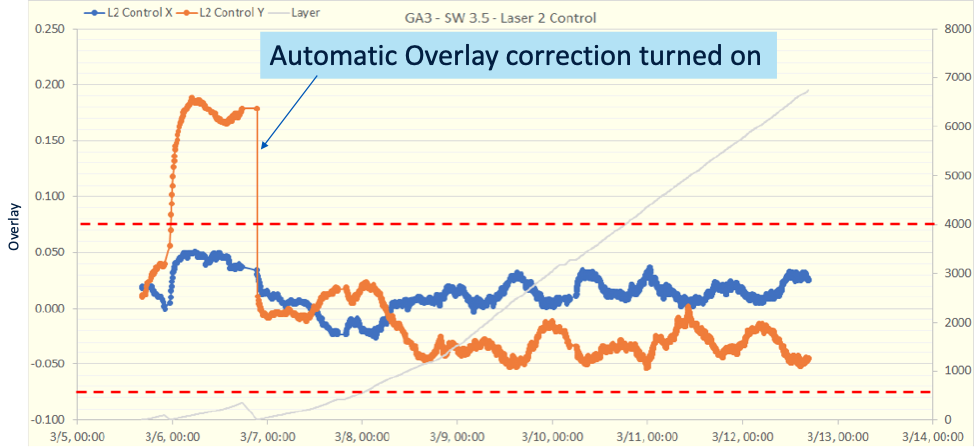
The solution we engineered is in situ laser calibration. By comparing the optics of the two lasers, our system can autonomously calibrate to ensure that the two lasers are in agreement on where the other is pointing. On a typical job, the Sapphire® system will automatically check its laser alignment every few layers, which undoes any drift before it becomes a problem. We can test the effectiveness of this system in any number of ways. In this example, we highlight the difference made by automated recalibration by printing a rectangular block with one laser building the top and bottom sections and the second laser building the middle. Without ongoing laser calibration, there is a visible offset in the middle section – good enough for a child’s block structure, but not for an aerospace application.
When we turn in situ monitoring back on, the piece is indistinguishable from one printed with a single laser. This is the standard that should be met to make dual laser printing viable for production applications.

Laser Utilization
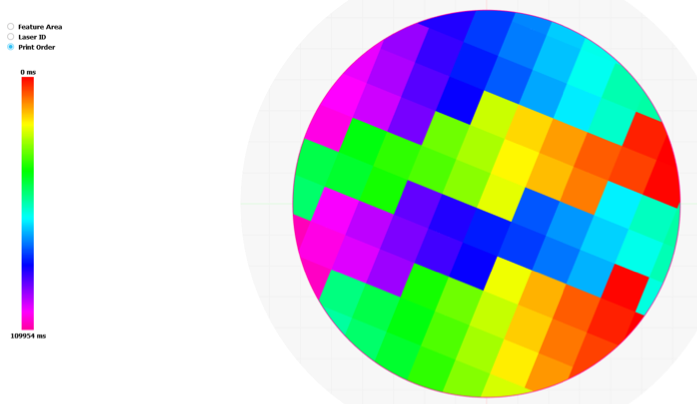
The main benefit of multi-laser systems is faster production. But this benefit is mitigated if one laser sees 100% utilization and the other sees only 50%. So, laser scheduling is critical to realizing the benefits of multi-laser systems. But it is not enough to just know that path of the lasers. Engineers must also examine how the laser soot effects the scheduling and how well the lasers coordinate their efforts on contour and core for larger parts.
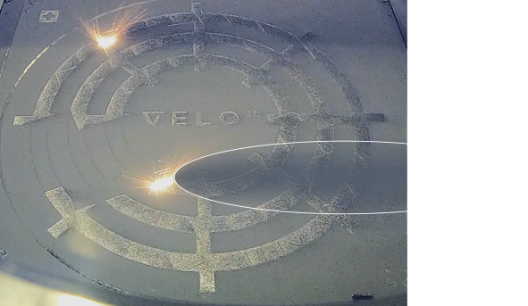
There are a set of related issues concerning soot management, gas flow and laser scheduling. A quick way to derail a build is by having one laser shoot through the soot cloud created by the other, and given the tight space we are operating in, each laser’s path has to be carefully planned to account for this. Shooting through smoke reduces the intensity of the beam when it hits the metal powder, which in turn can lead to poor mechanical properties. To ensure that neither laser gets in the others way, we employ a “swim lane” methodology in which each laser stays within one of two parallel tracks, and all track switches are synchronized. This programming allows us to run both lasers at all times during a build, meaning we take full advantage of the two-laser system.
A crucial engineering question with more than one answer is how to subdivide the work between the two lasers when they are each building one half of a solid part. If we imagine printing a cylinder, one option is to have one laser print the contour, while the core is split between the multiple lasers. Parts printed this way look good on the surface because there is no seam on the outer layer, but this approach can cause “sub-contour” porosity, and any structural issues tend to be hidden by the clean outer surface.
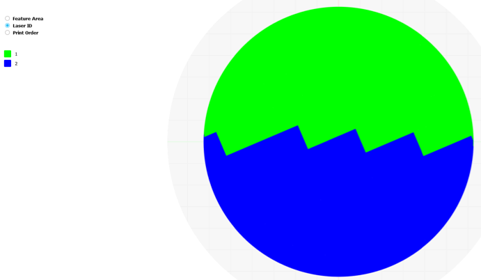
VELO3D’s approach results in a solution that makes overlay issues highly obvious. Our methodology results in each laser printing core and contour for half the structure (cylinder), with the two sides connected by a zig-zag line. The connection is jagged, not straight, to improve structural integrity. In addition, like a wall of offset bricks, the connection line moves with each layer, which further improves the strength of the piece. Since the contours are each built with their respective lasers and since the interface moves on each layer, if the lasers are not aligned, the surface finish of the part suffers. While this may sound like a negative, it means that any issues with overlay are immediately obvious in the printed part and not hidden beneath a smooth surface. Our automated calibration ensures that the laser overlay is within tolerance and that our surface finish remains unchanged in the overlay region. It also ensures high quality, non-porous metal for the core of the part.
Including a second laser on our printer presented a host of challenges from galvanometer drift to soot buildup, and the solutions required developments in hardware and software. What our team was able to achieve is a printer that can build complex parts with a wide range of angles, few if any supports, at twice the speed of a single-laser machine. The parts we make have to be good enough to keep a plane in the sky, and so we are meticulous in developing and testing every improvement we make to our system. In building a machine that gives each laser a dance partner, we had had to make sure they are constantly in step with one another. The result is a printer that affordably and quickly churns out high quality parts for our customers.