
New metal additive manufacturing technology enables support-free building
Nearly three decades after the industry’s first “what if” discussions on metal 3D printing, this now-mature technology has become the preferred option for numerous manufacturing needs, particularly those of the aerospace sector.
Topology optimization and generative design software, together with additive manufacturing’s (AM) ability to produce previously unimaginable geometries, create 3D-printed parts that are typically both lighter and stronger than their conventionally produced counterparts, reducing aircraft weight and cutting millions of dollars in fuel costs.
Because 3D-printed parts come out of the build chamber at near-net shape, there’s also less material waste, a factor that’s particularly important with titanium, INCONEL®, and other expensive aerospace alloys. Less material generally means less machining, further reducing production costs. What were once complex assemblies now can be printed as single units, simplifying the supply chain while improving component integrity. And because moulds, dies, and other such tooling is not needed to produce 3D-printed parts, manufacturing lead times are also significantly reduced, potentially shaving months or even years from product development cycles.
Noteworthy successes
It’s for these reasons and others that aerospace companies everywhere are embracing the ability to 3D print fully functional prototype and end-use metal parts.
Most in the industry have heard about GE Aviation’s 3D printing of more than 30,000 LEAP fuel nozzles, a move that reportedly cut the complex component’s cost by 30 per cent while providing fivefold greater durability. It’s a model success story, but what’s perhaps more notable is the company’s adoption of 3D-printed parts for its new Catalyst turboprop engine, condensing what would have been 800 conventionally produced components to just a dozen 3D-printed ones.
Similarly, aircraft manufacturer Airbus has begun using 3D-printed titanium brackets on the airframe of its A350 XWB commercial airliner, a first in the aviation industry.
Other manufacturers are following suit.
 Boom Supersonic is testing additively manufactured flight hardware for the XB-1 supersonic jet. The Ruag Group is 3D printing topology-optimized antenna brackets for Sentinel satellites. Rolls-Royce is 3D printing parts for its Trent XWB-97 engine, and the U.K.’s Orbex recently built the world’s largest 3D-printed rocket engine.
These are just a few examples of the ways that metal AM is taking us farther, faster, and more cost-effectively than ever before.
While metal AM has come a long way in aerospace, results can still be less than perfect—or at least a long time in coming because of necessary production reruns. Build failures are an all-too-common occurrence, leading to production delays, unplanned costs, and supply chain uncertainty.
The potential for porosity and layer delamination during the printing process requires manufacturers to validate part integrity with expensive and time-consuming CT or X-ray scanning. Lasers can fall out of alignment, recoater blades can crash into workpieces, and build chambers can leak just enough to make part quality questionable.
For all its capabilities, metal 3D printing has been, in many ways, a relatively immature process. Until now, that is.
Millions of operations
Ask any machinist, sheet metal worker, or manufacturing engineer and they'll all tell you the same thing: Lightweighting might be great and shorter lead times and lower production costs are every manufacturer’s goal. But if the parts are bad or quality inconsistent, budgets can be overrun. This is why robust process control is crucial, no matter what you’re making or how it's made.
Constructing parts with laser beams and metal powder raises this most basic of manufacturing tenets to an entirely new level. Metal AM can be thought of as a series of microsized welding operations. And with large workpieces, you could easily be performing millions of these operations, each of which must be as perfect as possible if you’re to achieve maximum material integrity.
Achieving that perfection has been an uphill battle for many equipment manufacturers, however. As suggested earlier, successful 3D printing is dependent on numerous factors, including reliable material deposition, accurate and consistent laser alignment, and stringent control of atmospheric conditions within the build chamber. These factors become even more critical as the workpiece grows larger, where the commensurately higher internal stresses caused by these "millions of welds" increase the likelihood of a build failure.
These goals are all quite achievable, provided the machine builder leverages the principles behind an entirely different type of manufacturing technology.
Purity is king
Much of the initial machine design work at VELO3D centred around the build chamber.
This is because the presence of oxygen and humidity within the build chamber has a profound impact on melt pool formation. It’s only by providing as pure an environment as possible that you get truly predictable surface tension and favorable wetting behaviors in the molten metal. Furthermore, it was discovered that higher oxygen levels during 3D printing cause brittleness and lack of ductility in certain materials. Together with the contaminants created during 3D printing, it can have a detrimental impact on the performance of parts built under those conditions.

Straight shooter
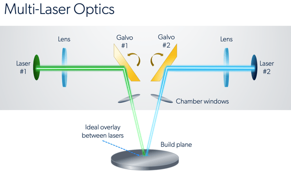
Even when soot and other particulates don’t occlude the laser beam, it doesn't guarantee that the beam is pointed at the right spot. To address this common problem, a sensor-based, closed-loop monitoring system monitors the melt pool’s thermal signature .. Based on this feedback, laser power can be adjusted in real time to maintain consistent temperatures, or the build halted if the system determines there’s a problem within the laser’s optical stack.
Proper recoating must be performed to maintain quality during the build. Some systems use a blade positioned 50 microns or so above the build surface, dragging fresh powder across the burgeoning workpiece. This can be a problem if bits of stuck-on material or minute lifting of the previous layer causes the blade to snag.
The consequences of this unfortunate event vary, but it can end up in a crashed build or even damage to the machine. There are other ways to perform this task.
A new way to build
The founder of VELO3D -- and many of its employees, myself included -- came out of the semiconductor industry. And even though the environmental and process controls used in chip manufacturing are way more stringent than those needed with metal 3D printing, we applied the same best practices when designing our hardware and software systems.
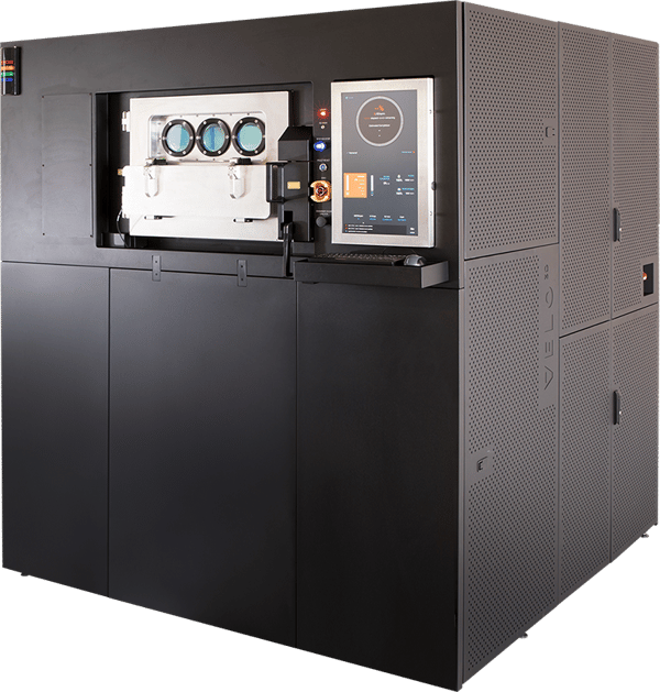
The company’s Sapphire printer has a 315-mm-dia. by 400-mm-high build chamber that is pressurized and able to attain oxygen levels of 1 PPM or less. It also uses a high-speed laminar flow system to remove the soot and other contaminants produced during the laser melting process. The result is an environment that promotes predictable lasing and reduces the potential for workpiece contamination.
Its recoater blade has a much higher clearance than incumbent metal AM systems This enables tolerance of all sorts of protrusions without a build failure. Often the process can actually take advantage of situations in which metal is sticking out of the powder bed. That's a big deal if you want to build parts in a support-free manner.
Breaking the rules
This last point—support elimination—is the holy grail of metal AM. Typically, metal powder bed machines require scaffold-like supports to anchor part surfaces shallower than 45 degrees, but some systems can print horizontal or nearly horizontal surfaces without such structures. This capability opens the door to creating more functional internal channels and chambers; large, horizontally-oriented holes; complex lattices; honeycomb shapes; and similarly demanding part geometries that were once impractical or even impossible to build.
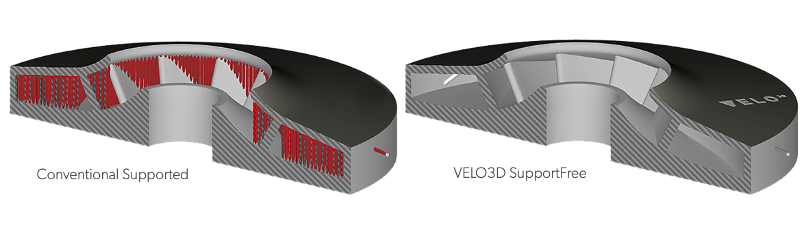
Support-free printing eliminates some or even all of the secondary machining needed to complete most 3D-printed parts. Perhaps more importantly, it removes the need to anchor most workpieces to a build plate. Not only is the post-process band sawing operation to free them eliminated, but the entire chamber now can be nested with free-floating parts, with far fewer constraints on workpiece orientation as well.
(originally appeared: https://www.canadianmetalworking.com/canadianmetalworking/article/metalworking/reaching-1-million-welds-with-am )