
Next-generation metal additive manufacturing does away with outmoded brazing methods and opens the door to optimized, high-performance geometries
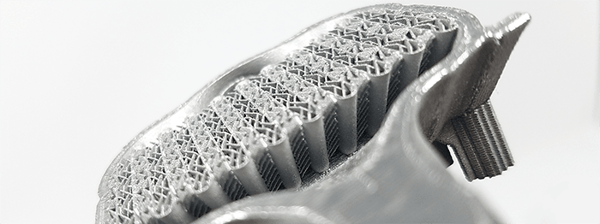
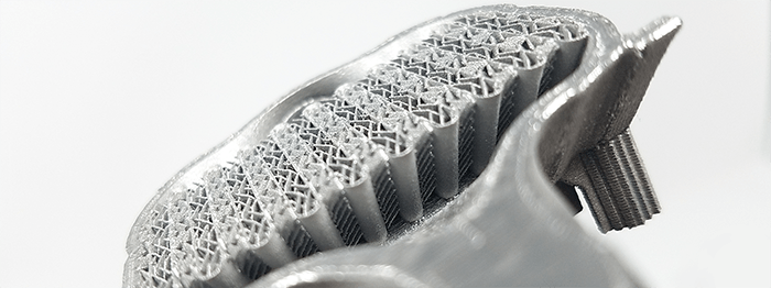
3D-printed heat exchanger demonstrates ultra-thin features in the core made possible with the latest advanced additive-manufacturing technology. This piece shows precision and fine features, made possible with 3D printing, that cannot be achieved through subtractive manufacturing.
Anywhere you find oil, fuel, or electronics in a high-performance vehicle, you are going to find a heat exchanger. For example, a typical commercial jet needs four to six heat exchangers per engine and the average commercial craft can contain 20+ heat-exchanger units overall. Drone design is about balancing tradeoffs between engine size and cooling-system weight to achieve optimum power and range. Satellites are crammed full of heat-generating electronics. Heat exchangers are everywhere.
The drawbacks of brazing
Clearly, heat-exchangers are essential for keeping aircraft of all types aloft and functioning properly. So why are we still making the vast majority of these systems using methods developed by the ancient Egyptians? Brazing, first employed by the Egyptians in 2400 B.C. for metal jewelry, joins different pieces of metal together with a coating of filler material.
Drawing from a wall painting in the tomb of the Vizier Rekh-mi-re at Thebes, dating from about 1475 B.C., shows a metal worker engaged in brazing in the workshop attached to the temple of Amun at Karnak

Until now the technology has been the standard for heat-exchanger manufacturing. Complex, multi-part assemblies (such as an array of cooling fins) can be brazed into a connected whole, with very little distortion, to exponentially increase the surface area available for heat dissipation and/or transfer.
But this “tried and true” methodology isn’t efficient. Most heat-exchangers used in aviation are still assembled largely by hand. This requires hours of skilled labor and multiple production steps. Part count can range from hundreds to thousands per unit. Brazing a finished assembly into a functioning whole takes place in dedicated vacuum ovens that must be carefully controlled for moisture and residual contaminants that can affect quality.
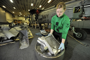
Aviation structural mechanic cleans and inspects a heat exchanger.
Credit: US Navy
And, once the engineer completes the brazing process, they still need to perform steps to achieve a finished assembly. Welding to headers - a high-precision, difficult to staff, expensive task with an average cost of $100 per weld joint; inspection; rework if necessary; vapor degreasing; and more welding may all be required to integrate the unit into a finished good.
Plus, it's messy. Brazing and welding commonly create byproducts of highly toxic substances—such as trichlorethylene, hydrofluoric acid, or hexavalent chromium. These substances are increasingly being controlled, if not banned, in the same countries that aircraft-related manufacturing facilities call home. The industry as a whole is looking to reduce or eliminate such chemicals without impacting quality and performance. But how? It’s time for a change.
Making the Future, One Layer at a Time
Leveraging a computer guided welding process called Additive manufacturing (AM aka 3D printing), engineers are able to print parts, layer-by-layer to create new structures from metal powder. First, a software program breaks down the digital part design into multiple processing steps that the printer executes. This is called slicing. Once sliced, the printer will run a set of pre-programed patterns, melting the powder layer-by-layer into a fully dense, finished part. Because 3D printing takes place within an inert, sealed chamber, no toxic by-products are released into the air, reducing the environmental footprint.
In addition, a wide array of digital designs can be printed. So, rather than print just a single part, you can consolidate multiple parts into a combined assembly. This enables engineers to reduce part count from hundreds of separate parts down to a single, multi-functional part. You can cut assembly times and make lighter and stronger designs. Almost anything that can be digitally designed can be printed at the push of a button. In theory…
Current AM Learning Pains
In spite of the benefits, AM has not taken over the manufacturing landscape. Why is that? A variety of aircraft, from both leading manufacturers and competitive startups, are already flying with some 3D-printed parts. But the bulk of aerospace and defense companies are looking ahead to more advanced, higher-performance designs with complex geometries. These designs are proving difficult for current 3D printers.
Most AM printers today have limitations. Due to the layer-by-layer process, the repetitive melting and solidification of metal causes stress accumulation. For example, if you were to print a flat strip of metal in a typical printer, the stress would eventually pull the metal up into a loop or ring shape. This has led to design rules for AM engineers. Low overhangs, or flat parts require supports – printed metal beams that work like metal staples to hold the part down to a build plate. This prevents designers from using unsupported angles of less than 45-degrees to the build plate. This is known as the “45-degree rule” and impacts enclosures and inner diameters similarly.
.jpg?width=450&name=Support-structures-45-degrees-Protolabs-300x174%20(1).jpg)
The second limitation has to do with the hardware. When typical printers move through the z-orientation of a part, they deposit and planarize new layers of powder. This is called recoating. To create a flat plane of powder, the printer scrapes away the excess with a recoater blade. Unfortunately, due to the thin nature of the powdered layers, if the part deforms (due to accumulated stresses), it can protrude above the desired powder height and contact the recoater. This can cause damage to the part, the recoater blade, or even fault the build completely. This results in limitations around aspect ratios for metal parts. The limit for most printers today is around an 8:1 aspect ratio.
SupportFree – The “Must Have” Feature for Metal AM
But to build the latest generation of combined assemblies and higher performance heat exchangers, engineers need to push beyond these limitations. Enclosures cannot function properly with metal support beams printed throughout their internal passageways. And once removed (if even possible to remove) the thicker, rougher surfaces produced by supports can interfere with the efficient flow of liquids and air. Furthermore, thinner is better when evaluating heat exchanger designs and, for the highest performance, an aspect ratio of 8:1 is no longer competitive.
These are the challenges that VELO3D started to address over 5 years ago. Today, our SupportFree capabilities and non-contact recoater technology have unlocked innovations in space, aviation, motorsports, oil and gas, and power generation. With support for leading Nickel, Titanium, and Aluminum-based superalloys, we are driving next generation manifolds, diffusers, impellers, and heat exchangers. Some of the advantages include:
- No supports required for many geometries down to zero degrees (horizontal)
- Smoother surface finish straight out of the build with no need for elaborate refinishing
- A non-contact recoater that is protrusion tolerant
- A detailed metrology suite to monitor part quality layer by layer
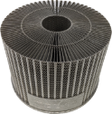
Radial heat exchangers like the one above are extremely difficult to manufacture and print due to the thin, circular fins; geometries that are tall and thin (high aspect ratio) typically have a high fail rate on existing 3D metal printers. Printed in Nickel-based alloy IN718
The shift of the heat-exchanger supply chain from a manual, non-differentiated processes to the state-of-the-art in AM technology is happening today. VELO3D can enable you to print low angles, high aspect ratios, and wider inner diameters, SupportFree. This combined with a layer-by-layer quality tracking solution enables a true “evolution” in heat exchanger design and manufacturing. I’m looking forward to seeing what the industries will unlock with our technology.